IP routing process is a fundamental concept in networks.
Having a clear understanding of IP routing process helps
network engineers troubleshoot complex network problems.
A good hold of this concept also helps determine end to end
traffic flow from any given source IP towards target IP.

Below are key steps
when traffic from source tries to reach the destination web server:
1.
All
the routers will perform route recursion for the destination
IP of the web server.
And
what exactly is route recursion?
Route
recursion is the process of determining outgoing router interface for
corresponding destination IP of packet.
Route recursion on router R1 will determine the outgoing interface as E1 for traffic
from source to destination web server in figure above.
2.
Longest
prefix match is always used.
This
means that if the route for destination web server 10.0.0.1 is learnt via two prefixes –
10.0.0.0 / 24 and 10.0.0.0 / 29, then the route for 10.0.0.0 / 29 is used since
it is more specific.
3.
Since
all the segments are Ethernet, ARP resolution is done in case of missing ARP
entry of neighbor IP.
4.
Layer
2 headers are re-written at each layer 3 hop. Which means that when router R1 sends the traffic to router R3, source
MAC will be MAC address of interface E1 of router R1 and destination MAC
address will be MAC address of interface E0 of router R3
5.
TTL
value of IP Packet is decremented at each layer 3 hop.
When
the IP packet crosses router R1, TTL value is decremented by 1.
6.
Additionally,
since the IGP is diagram above is OSPF, DR/BDR election will occur on each
Ethernet segment by default.
Remember,
DR/BDR election occurs on Broadcast network types. This is done to minimize LSA
replication and to save CPU/memory of involved routers.
Since
the segment between R1 and R3 does not involve more than 2 routers, DR/BDR
election can be prevented by setting the OSPF network type of involved
interfaces as ‘point to point’
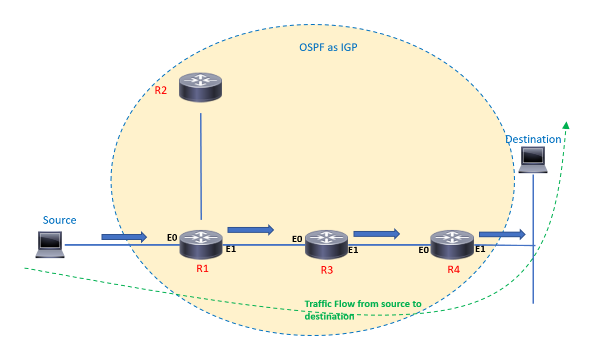
In the figure above, source is trying to reach the
destination web server.
Source determines that the destination is not connected to
the local segment, hence sends the IP packet to router R1 which is its default
gateway.
Source will check its ARP cache and in case there is no entry for
the default gateway, source will ARP the MAC address of interface E0 of router
R1.
When source sends the traffic to the gateway, source MAC
address is the hardware address of its Ethernet adapter and destination MAC
address will be MAC address of interface E0 of router R1.
Router R1 will check its routing table, will look for
longest prefix match and will perform route recursion.
Here, router R1 will determine that it needs to send the
packet through interface E1 to reach the destination.
TTL value is decremented and the IP packet moves towards
router R3
From router R3 onwards, the above process is repeated until
the IP packet arrives at the destination web server.
No comments:
Post a Comment