Showing posts with label Routing. Show all posts

Thursday, August 30, 2018

OSPF NSSA


In the topology above, routers R1 and R2 are the ABRs interfacing with backbone area 0

Area 1 in this topology has been configured as NSSA this time. My earlier topology referenced a Totally NSSA area.


As mentioned earlier, NSSA configuration in OSPF allows redistribution to occur within the NSSA area.

These redistributed prefixes are Type 7 LSAs and are converted to Type 5 LSAs as they are injected in area 0 by one of the ABRs interfacing area 0

Router with higher router ID is elected to do this translation where there are multiple ABRs interfacing backbone area 0


Like stub area, Type-5 external LSAs are blocked from entering the NSSA area.
Compared to Totally NSSA, area configured as NSSA will not filter Type 3 LSAs and will only filter Type 4/Type 5 LSAs.

As opposed to Totally NSSA; in the case of NSSA, the default route is not auto injected.

And this needs to be injected manually using command area <area_id> nssa default-information-originate


===================================


Area specific configuration on routers R1, R2, R3 and R4 is as below


Configuration on Router R1

Conf t

Router ospf 1

Area 1 nssa default-information-originate


Configuration on Router R2

Conf t

Router ospf 1

Area 1 nssa default-information-originate metric 100


Configuration on Routers R3 and R4

Conf t

Router ospf 1

Area 1 nssa


For demonstration purpose, note in the above configuration of Router R2, we have increased the metric of default route to 100

This will force traffic from routers R3 and R4 to follow the default route of Router R1 since route from R1 has lower metric.

We are just trying to cover this use-case whereby you can force the traffic through one of the upstream routers in case there is a better WAN link there.

Below output shows default route on router R4
Default Route on Router R4

Below output shows clearly that metric through Router R1 is lower as compared to Router R2
 

=======================================


If you want the traffic moving from R3/R4 towards backbone area 0 to be load balanced across R1/R2, then there is no need to increase the metric of default route on R1/R2

In that case, OSPF topology information for default route on Router R4 will be as below.

Monday, January 16, 2017

IP Routing Process


IP routing process is a fundamental concept in networks.
Having a clear understanding of IP routing process helps network engineers troubleshoot complex network problems.
A good hold of this concept also helps determine end to end traffic flow from any given source IP towards target IP.


Below are key steps when traffic from source tries to reach the destination web server:

1.       All the routers will perform route recursion for the destination IP of the web server.
And what exactly is route recursion?
Route recursion is the process of determining outgoing router interface for corresponding destination IP of packet.
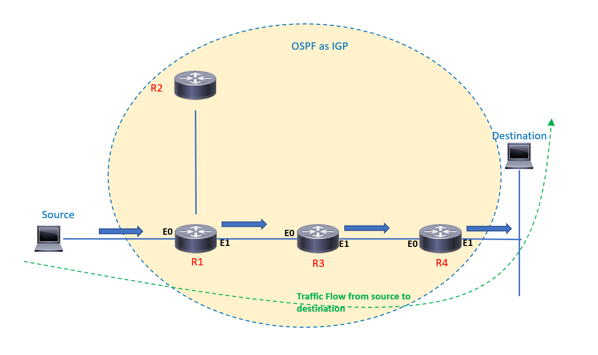
Route recursion on router R1 will determine the outgoing interface as E1 for traffic from source to destination web server in figure above.

2.       Longest prefix match is always used.
This means that if the route for destination web server 10.0.0.1 is learnt via two prefixes – 10.0.0.0 / 24 and 10.0.0.0 / 29, then the route for 10.0.0.0 / 29 is used since it is more specific.

3.       Since all the segments are Ethernet, ARP resolution is done in case of missing ARP entry of neighbor IP.

4.       Layer 2 headers are re-written at each layer 3 hop. Which means that when router R1 sends the traffic to router R3, source MAC will be MAC address of interface E1 of router R1 and destination MAC address will be MAC address of interface E0 of router R3

5.       TTL value of IP Packet is decremented at each layer 3 hop.
When the IP packet crosses router R1, TTL value is decremented by 1.

6.       Additionally, since the IGP is diagram above is OSPF, DR/BDR election will occur on each Ethernet segment by default.
Remember, DR/BDR election occurs on Broadcast network types. This is done to minimize LSA replication and to save CPU/memory of involved routers.
Since the segment between R1 and R3 does not involve more than 2 routers, DR/BDR election can be prevented by setting the OSPF network type of involved interfaces as ‘point to point’


In the figure above, source is trying to reach the destination web server.
Source determines that the destination is not connected to the local segment, hence sends the IP packet to router R1 which is its default gateway.
Source will check its ARP cache and in case there is no entry for the default gateway, source will ARP the MAC address of interface E0 of router R1.
When source sends the traffic to the gateway, source MAC address is the hardware address of its Ethernet adapter and destination MAC address will be MAC address of interface E0 of router R1.

Router R1 will check its routing table, will look for longest prefix match and will perform route recursion.

Here, router R1 will determine that it needs to send the packet through interface E1 to reach the destination.
TTL value is decremented and the IP packet moves towards router R3

From router R3 onwards, the above process is repeated until the IP packet arrives at the destination web server.